
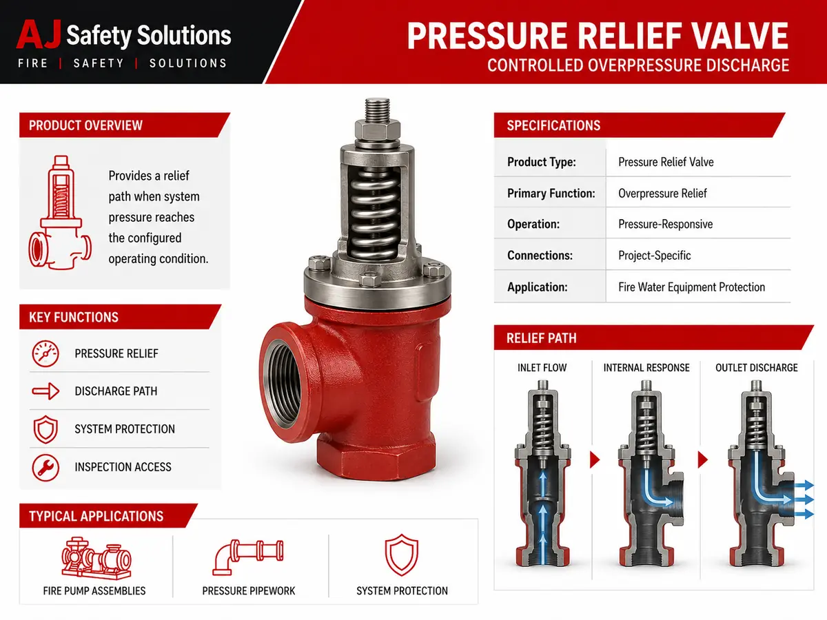
Pressure Relief Valve for Fire Water Equipment Protection
A pressure relief valve provides a controlled discharge path when pressure at its inlet reaches the configured operating condition. The valve responds through its internal mechanism and directs water toward the connected relief outlet according to the system design. It is intended to support overpressure management, but correct protection depends on verified sizing, setting, discharge routing and integration with the complete installation.
Coordinate the valve requirement with AJ Safety Solutions, compare the related gauges and instruments, and match the arrangement with compatible hose reel and fire water equipment.
Pressure-Responsive Relief Path
The inlet communicates system pressure to the internal operating element. When the model’s configured condition is reached, the mechanism opens a path toward the discharge connection. As conditions change, the valve responds according to its design and adjustment. Discharged water must be routed safely and must not create an uncontrolled hazard.
Functional Features
- Provides a defined path for pressure-relief discharge.
- Pressure-responsive mechanism operates according to the configured model.
- Identifiable inlet and outlet support correct system coordination.
- Accessible body and bonnet areas support inspection and maintenance planning.
Typical Applications
Pressure relief valves may be coordinated with fire pump assemblies, pressure-controlled pipework, hose reel systems, test arrangements and other approved fire water equipment. Selection requires understanding of the maximum expected condition, required relief duty, back pressure, discharge destination and applicable project criteria.
Specification and Installation Notes
Set pressure, adjustment range, inlet and outlet size, connection type, flow capacity, pressure rating, body material, trim, sealing, temperature limits, orientation, drain arrangement, certification and approvals are model-specific. No numerical setting, capacity or material grade is asserted in this generic record. Use verified manufacturer data and approved calculations before selection or publication.
Inspection and Standards Context
Keep the discharge path unobstructed and inspect for leakage, damage, corrosion and unauthorised adjustment under the approved maintenance programme. Consult NFPA 14 for relevant standpipe and hose system requirements and NFPA 25 for inspection, testing and maintenance guidance. Adopted codes, approved design documents, manufacturer instructions and the authority having jurisdiction remain controlling.

Reviews
There are no reviews yet.